MrCocoNuat
Nice Cockcroft-Walton
Ok, jokes aside - the Cockcroft-Walton Multiplier is a design that generates DC from AC, charging up N stages of capacitors sequentially while keeping them in series so that the final output voltage achieved is as high as N*Vpp. To understand this, think of those old toys where figurines would slide down a track until they hit a staircase, and like magic, a constantly oscillating motion could move them all the way to the top for them to slide down again.

In this circuit, the input AC is the oscillating motion and electron front is the penguins - as each capacitor is charged by one half-wave (C1 first), the next half-wave pushes the particular stack ending with that capacitor to a high enough voltage to exceed that of the other stack, and so the next capacitor in sequence can charge (here, C2). After many iterations (remember that C1 will lose voltage charging C2, so the overall process isn’t quite that fast), each of the capacitors in the output stack (C2, C4) holds Vpp, and the output is generated!

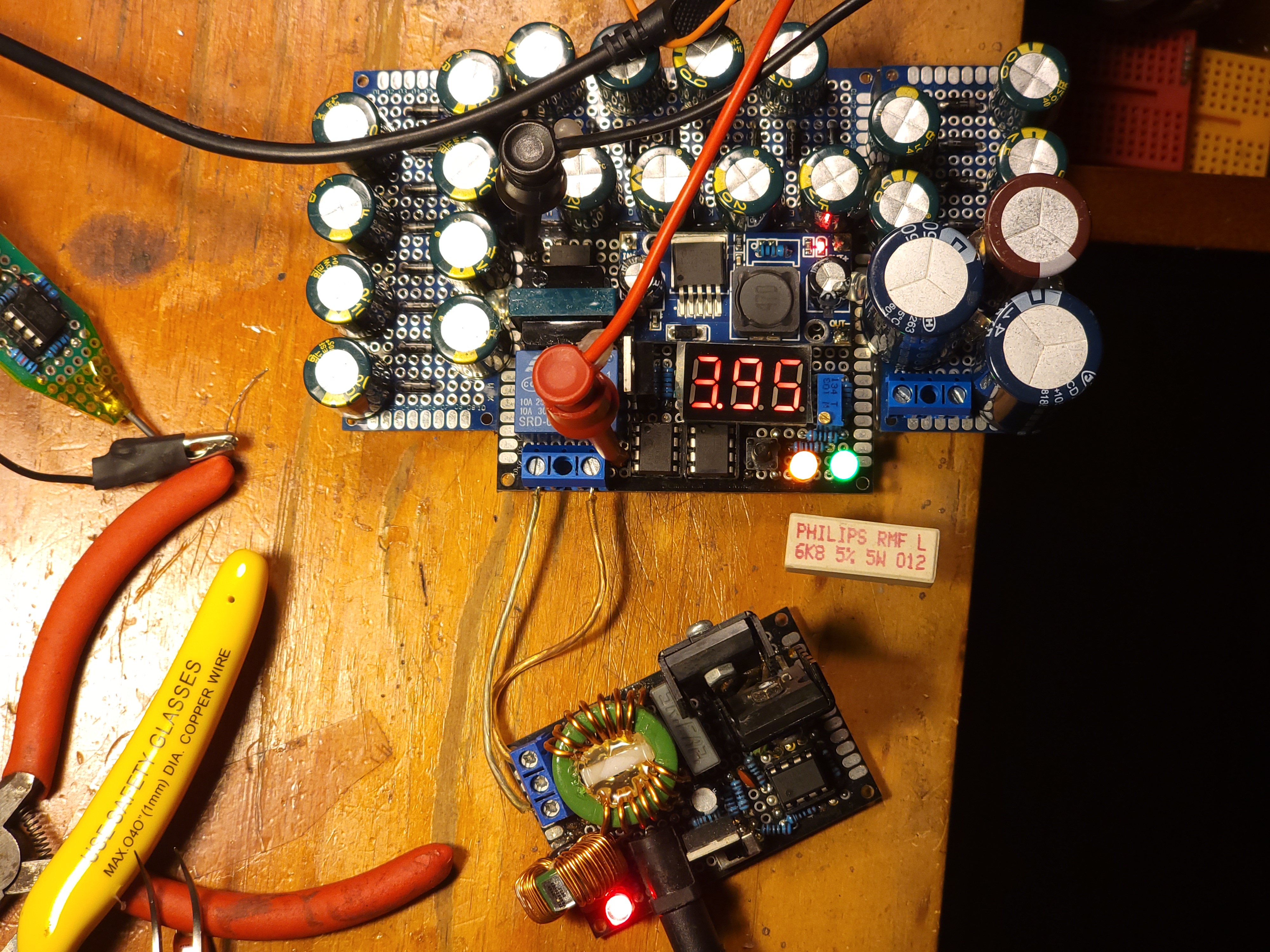
With a output frequency around 20kHz, the ZVS driver is almost ideally suited for supplying this generator. You can send power through a HV transformer first, so that Vpp = 10-20kV and use corresponding high voltage diodes and capacitors, or pipe the 60Vpp directly into a low voltage but higher power version of the circuit. That is what I did.

(don’t worry, every part is explained thoroughly)
Risks
Sure, this is LowTierTech, but that doesn’t mean it has to be LethalTierTech~
In rough order of danger, the risks I wanted to control against were:
- Explosion of the main power capacitors, charged at 450V they can do a lot of damage!
- Exposure of up to 400V on the output terminals
- Wire overcurrent leading to fire
In turn:
- I wanted a hard-switch to disconnect the capacitor chain, and this really had to be hard. Considering the required specs (
60VAC, able to break10A) a mains-class relay was the obvious choice. But this necessitates the integration of control electronics! - I used a 3-port shrouded screw terminal, but with the middle post and screw completely removed. This provides sufficient isolation both between the output terminals and to the outside world. Additionally, during testing and use, make sure to have a rapid discharge resistor handy. It must be capable of dumping all the output energy into heat, so I suggest a
5kOor so power resistor, which should be just fine absorbing a400Vcapacitor. - …realistically this is not likely to happen. Just don’t be stupid, use at least 18AWG or something to handle
10Abursts.
Control Electronics
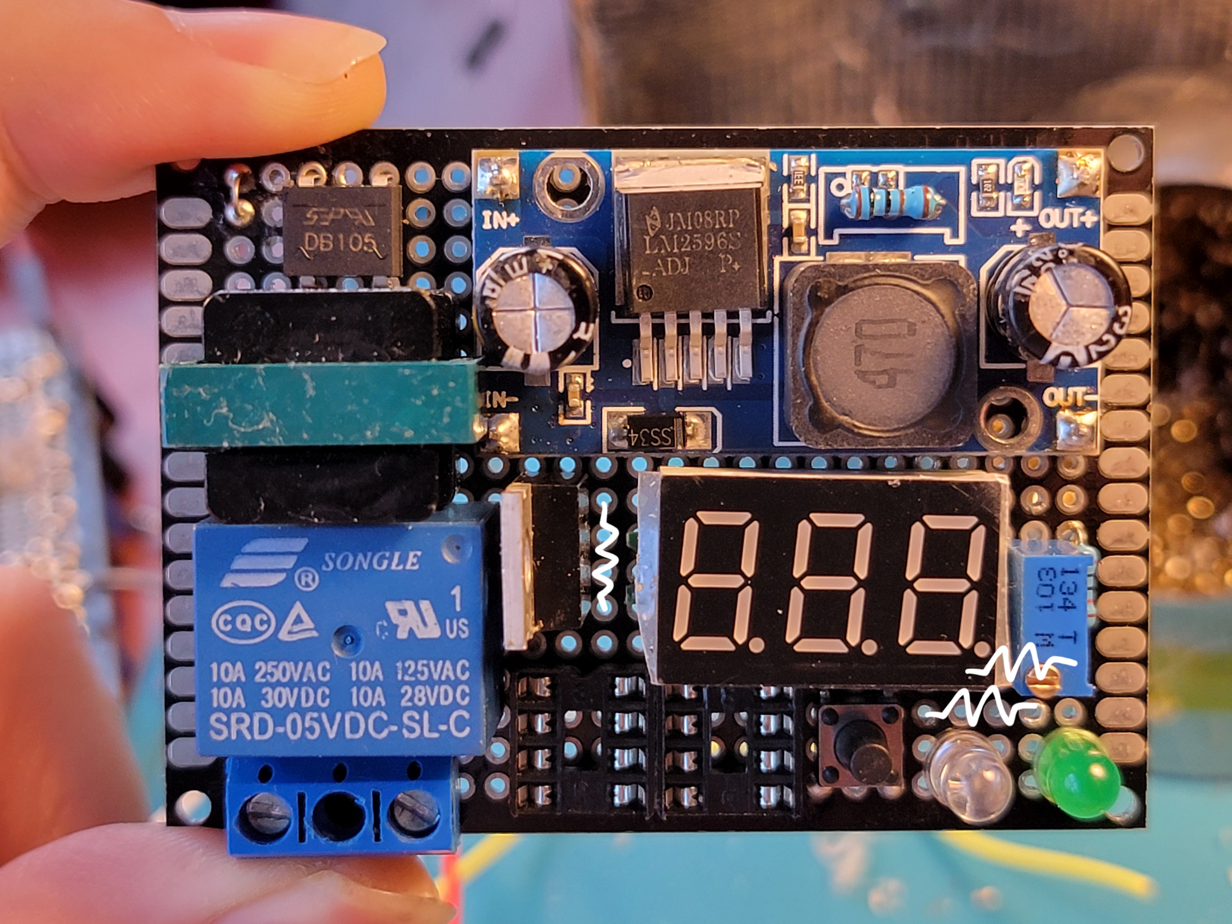
With the introduction of a relay on the input side, I needed a microcontroller to control it. Of course, I picked my beloved ATtiny85 for the job. It however demanded payment of 5VDC, which I certainly could not get directly from the input AC. No matter - I put a basic isolated converter consisting of a transformer, rectifier, and buck converter between them, this makes it possible to define my digital GND anywhere on the capacitor chain and measure voltages between any 2 points, which is necessary to sense the actual output voltage.
The actual voltage sensing is done through a 1:100 resistor divider (which also acts as a bleed resistor for the main capacitors) to limit the range to 0-4VDC, then through a buffer to provide minimal output impedance before being delivered both to the microcontroller and a miniature display voltmeter with the decimal point blacked out to increase the displayed number by 100 times - these are nifty little gadgets!
As for I/O, the microcontroller gets 1 input button on pin 2 external interrupt (remember to add a debouncing capacitor, I initially forgot), and a output to the relay’s coil through a FET. Remember the flyback diode for the coil! Finally, 2 status LEDs give the user an idea of how the overall converter is doing.
A bonus feature is an adjustable output voltage, which I achieved with a trimmer potentiometer attached to the microcontroller’s RESET pin.
Power Electronics
The main limiting design parameter to this whole project was the high voltage capacitors - it’s pretty difficult to dig out anything more than 450V, since that is what 240VAC mains rectified is safely under. Therefore, I used my long-salvaged power supply capacitors for this converter, totalling 450uF which is a pretty scary amount of energy: 0.5 * 450uF * 450V^2 = 36J.
With my input maxing out at around 60Vpp, that meant I should use 8-10 stages to quickly reach this maximum 450V, so I picked 10. Simply hooking up 10 pairs each of diodes (at this voltage, ordinary ones are fine) and capacitors finished this part of the build. But hoo boy this was a lot of soldering identical modules together…
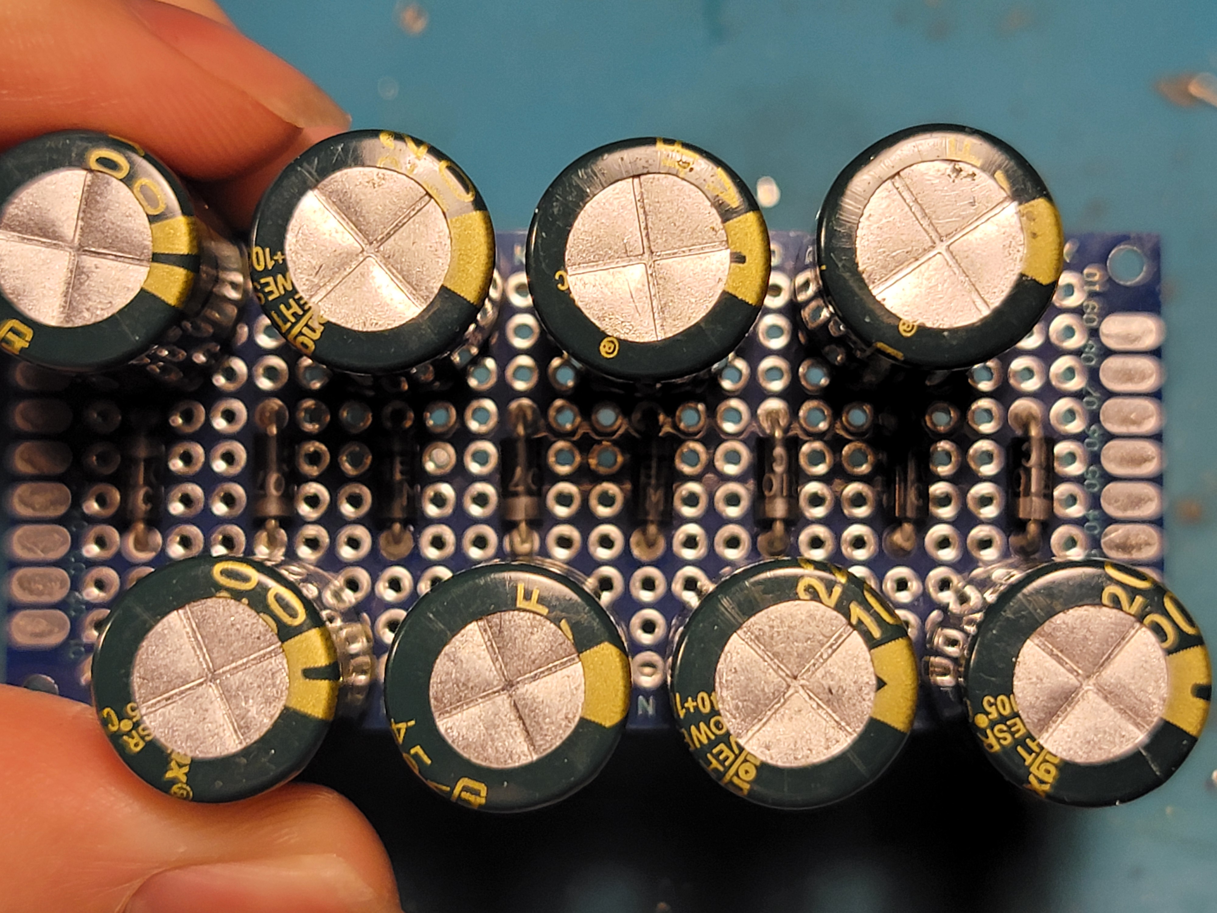
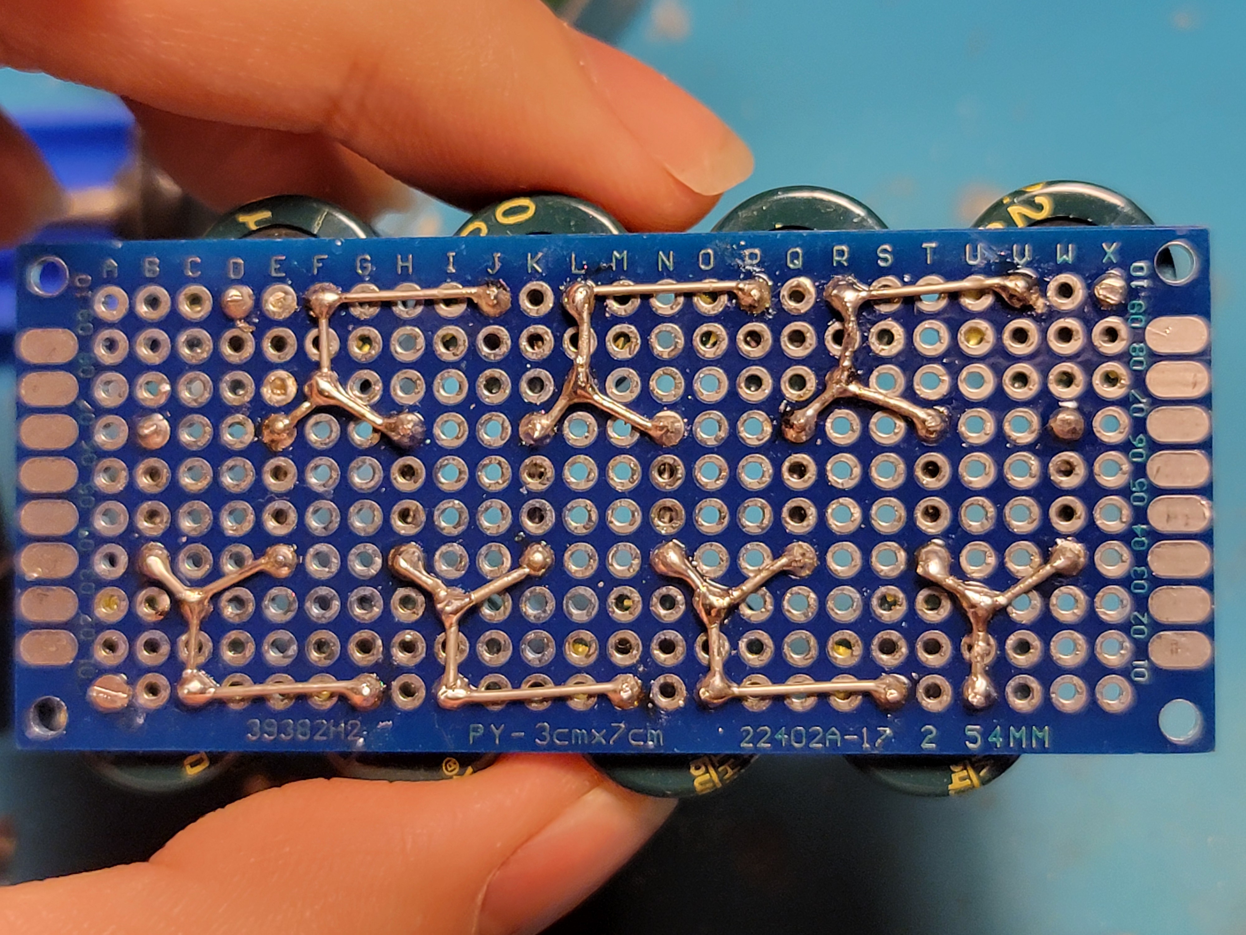
Hooking it up to the input relay, make sure to connect it to the normally open line, that way with no microcontroller authorization, the relay will not give power to the capacitor chain.
Soft Start
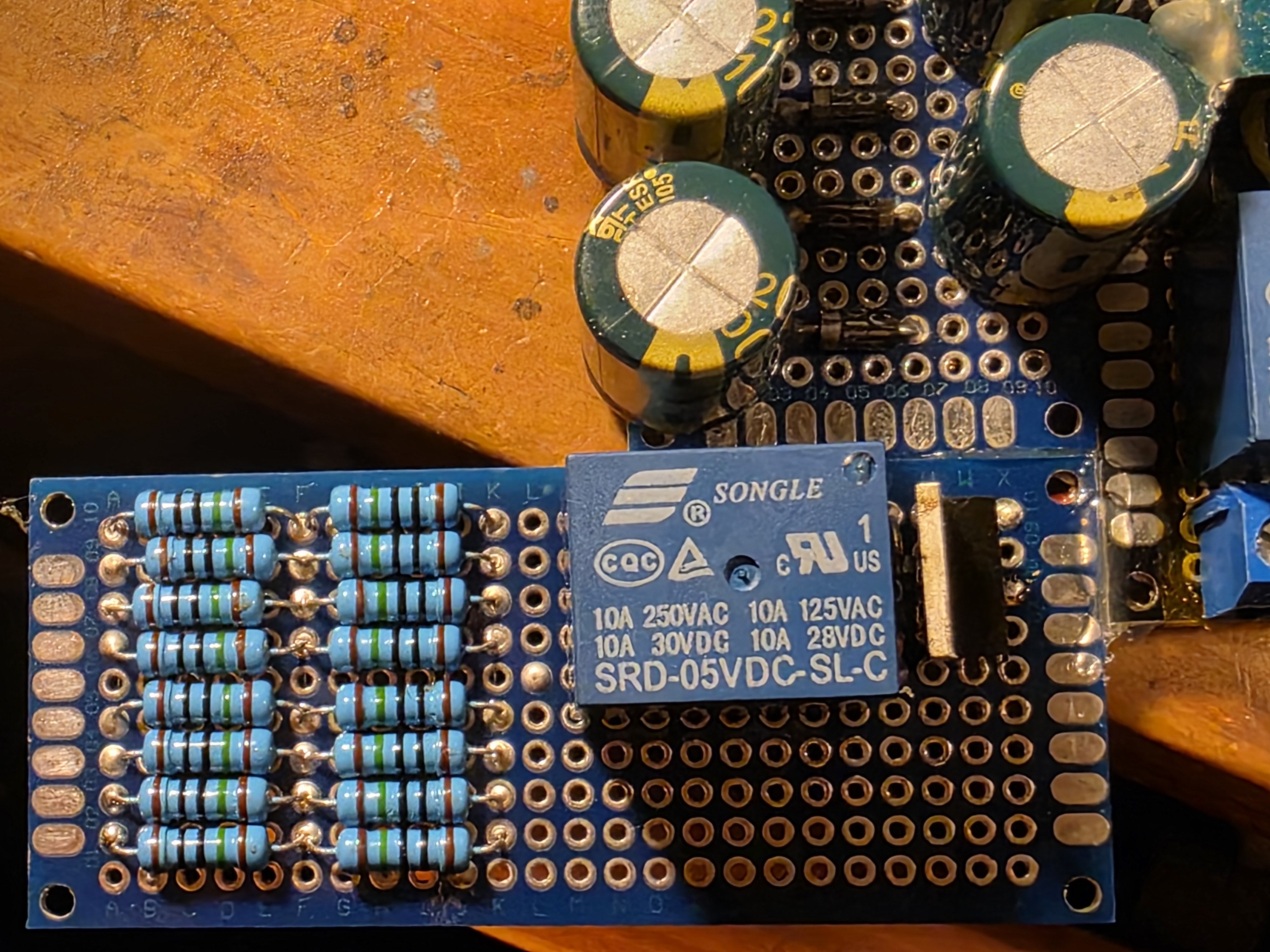
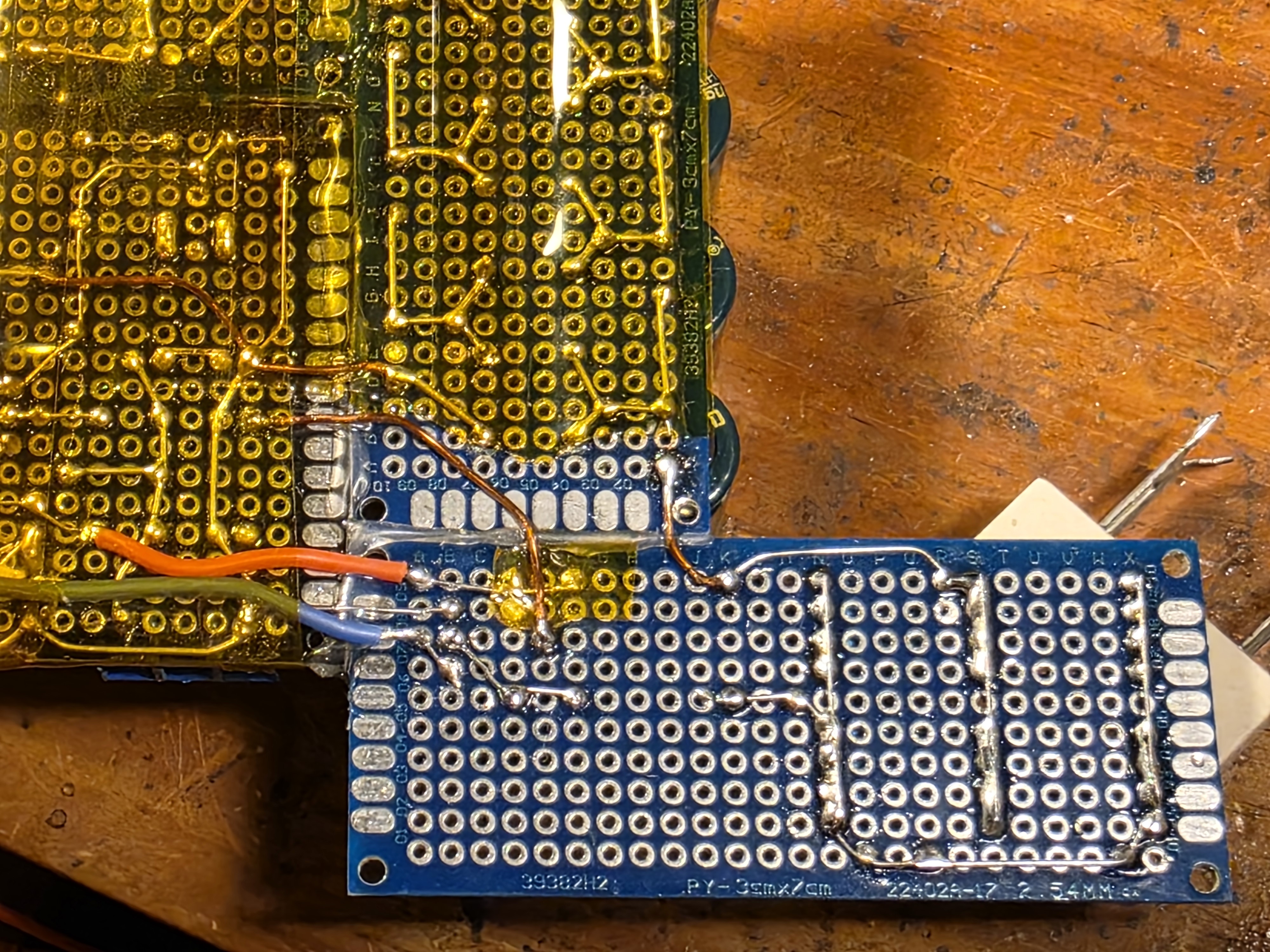
This hardware did work, but not consistently. The issue with capacitor-based generators is that when at 0V, they appear essentially like a short circuit on the input, which caused my AC driver to fail upon trying to supply the massive inrush current. The solution here was simple enough - at these power levels, a beefy 10O or so soft start resistor on the input to the capacitor chain will work just fine to limit the inrush current. I used 16 large 150O resistors in parallel in the output path of the main relay to make sure that even if the resistors were stuck in the power path (say the bypass relay failed), destruction wouldn’t be immediate, but this was probably overkill. After the microcontroller decides that enough voltage has built up in the generator system so that bypassing the soft start resistors won’t cripple the power source, it does so with another relay.
Software
I implemented the control software via a state machine. The microcontroller keeps track of its current state (e.g. IDLE, CHARGING, CHARGED) and constantly checks the output capacitor’s voltage and button input to figure out its next state transition. Additionally each of the states has a unique LED illumination effect (e.g. BREATHE, BLINK, ON) so the user knows what is going on.
A safety measure is that whenever the output capacitor’s voltage rises above the absolute maximum set voltage (e.g. 420V for 450V capacitors), the state immediately changes to ERROR and locks there, cutting off further power.
Assembly
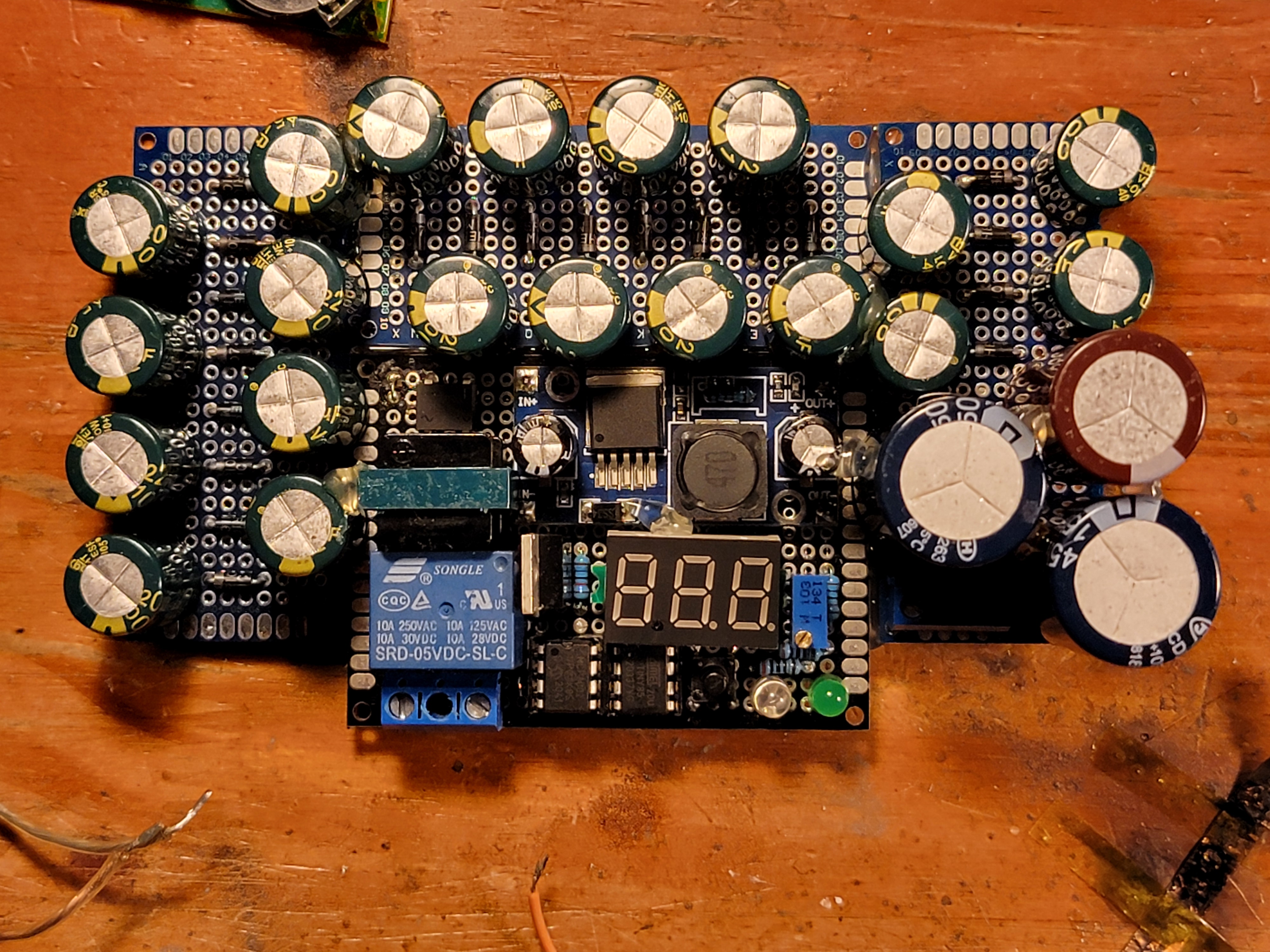
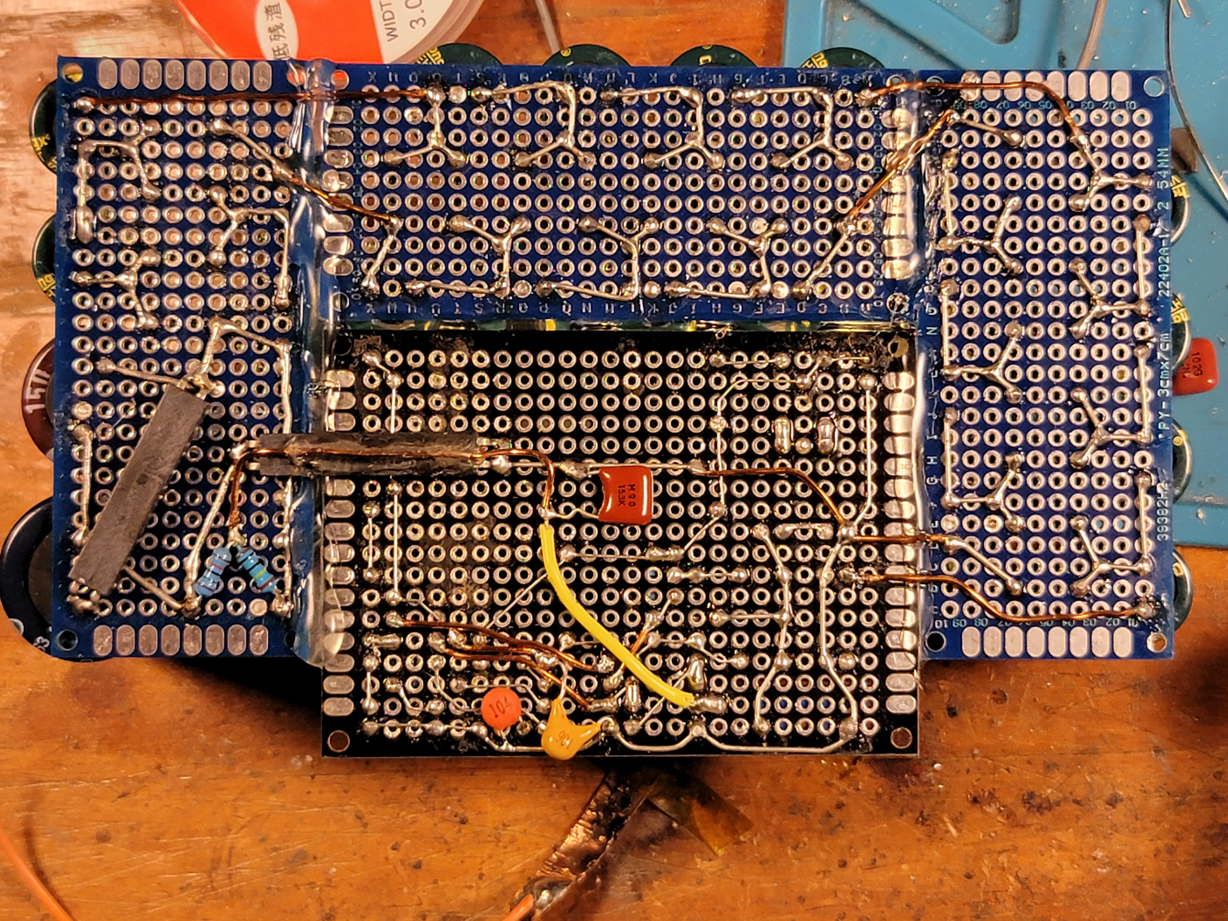
I built this converter on several protoboards, with absolutely no faith that all the necessary components would fit onto just 1. No matter, hot-gluing them together and using nice sturdy magnet wire for cross-board connections worked just fine.
And this converter turned out quite powerful, capable of easily sustaining 80W of output at 400V, although my test load sure wasn’t capable of taking it… oops!
